Week 5
ADKeypad
⦁ Take a cord and connect one end to port one of the Micro:Bit and the other end to the ADKeypad. The ADKeypad has two red buttons and three blue buttons on it.
⦁ Basic Setup
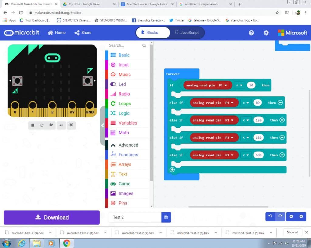
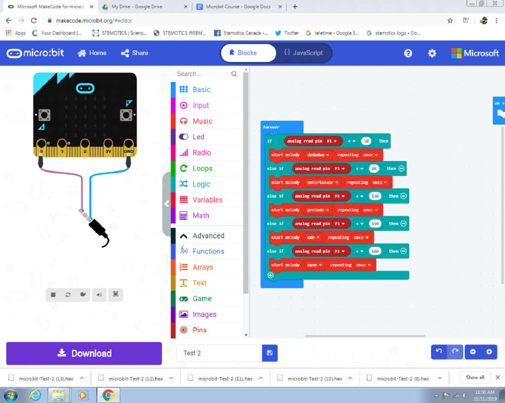
We’ll start by creating the basic program for the ADKeypad. First, you’ll need an “if else” block, which can be found in the Logic menu. The “if else” block should have five sections, one for each button on the ADKeypad. Next, you will need a “Less Than” block with an “Analog Read Pin” block set to P1 on the left side for each section. The number on the right of the equals block indicated which button the result is directed to. The number 10 directs the result to button A, 80 directs the result to button B, 130 directs the result to button C, 160 directs the result to button D, and 600 directs the result to button E. Put a different number on the right side of each “Less Than” block, preferably from lowest to highest.
⦁ Using the ADKeypad To Play Tones
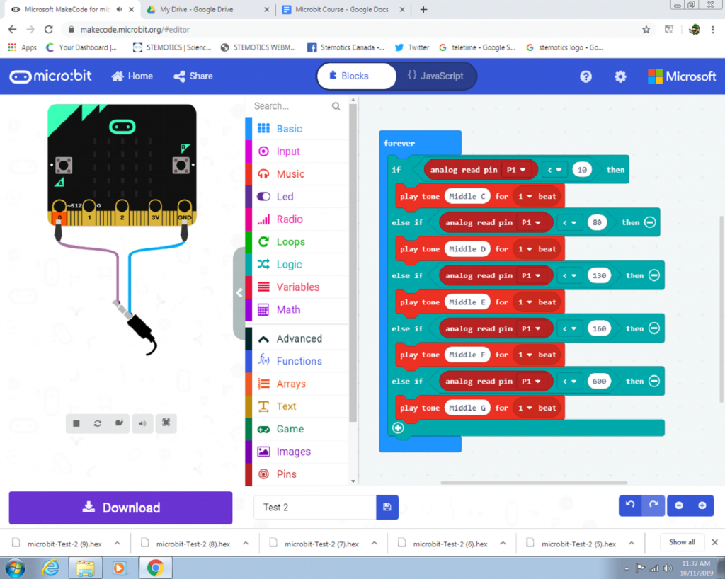
Now that we have the basic program set up, now put a “Play Tone” block into each section of the “if else” block. Set each tone block to a different pitch. When you download the program, the Micro:Bit should play a different tone depending on which button on the ADKeypad you press.
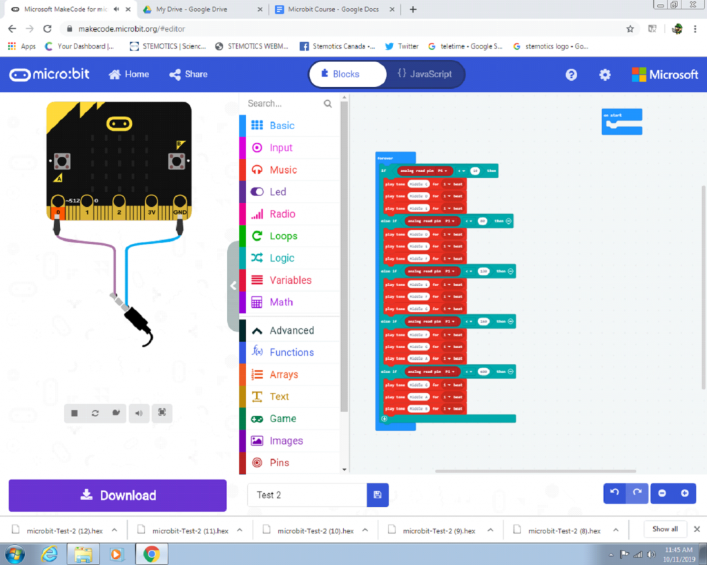
⦁ You can also make multiple tones play in a row when you press a button.
⦁ Or assign a preset melody for each button.
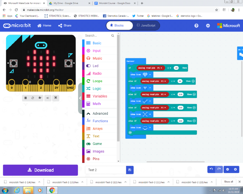
⦁ Now, instead of using the buttons to play tones, try putting “Show Icon” blocks into the program. When the program is downloaded, pressing each button should display a different icon.
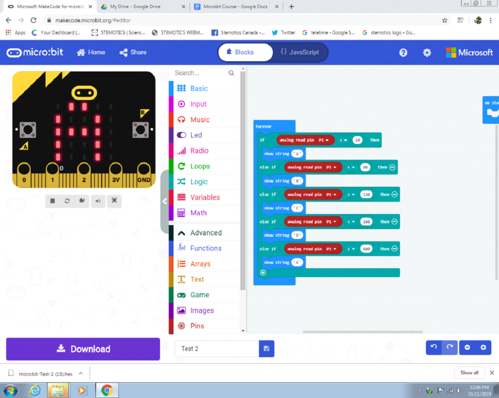
⦁ Now try putting “show string” blocks into the program, so each button will display a different letter.
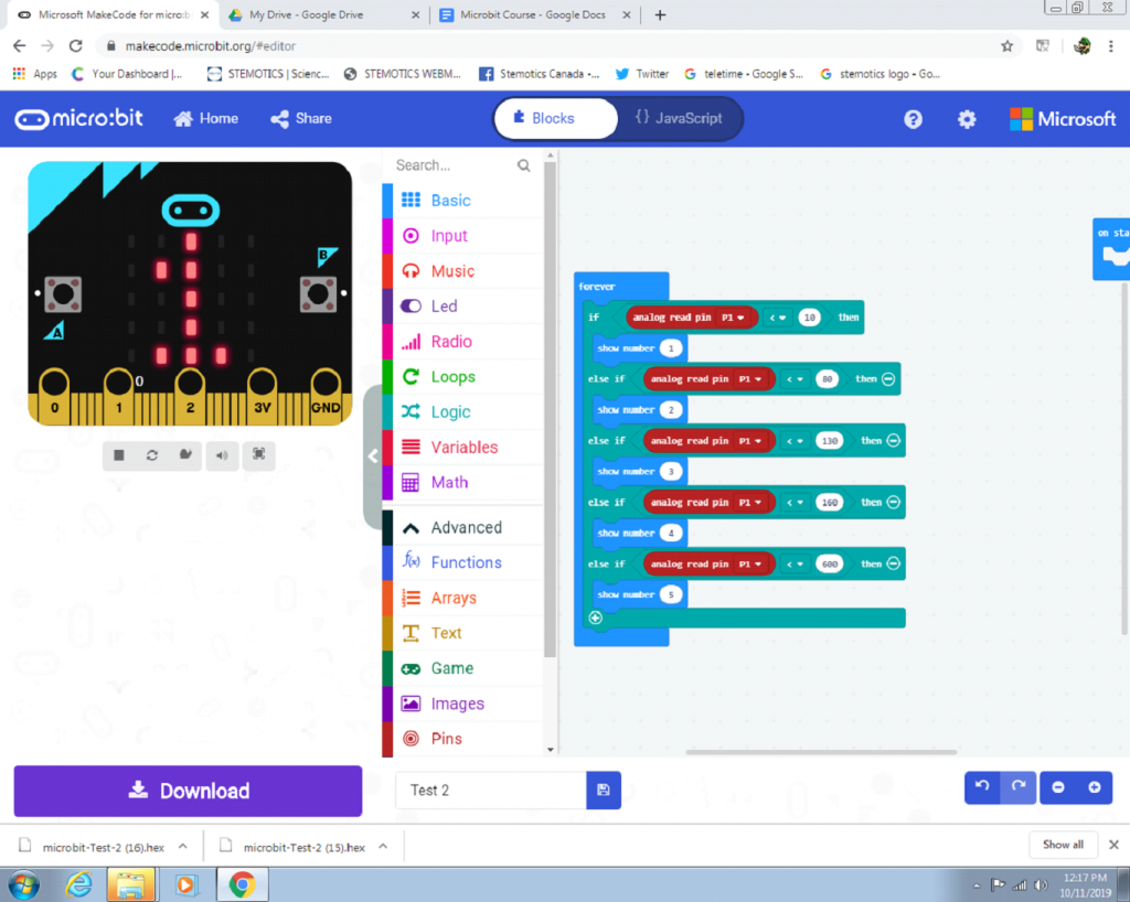
⦁ Now put “show number” blocks into the program so that each button displays a different number.
⦁ Now that you know how the AD Keypad works, try creating different combinations of music, sounds, icons, words, and numbers to assign to each button. Just be creative and let your imagination flow.
Potentiometer
⦁ The Potentiometer is an attachment for the Micro:Bit that has a blue knob that you can turn. Get a cord and attach one end to port one on the Micro:Bit and the other end to the Potentiometer.
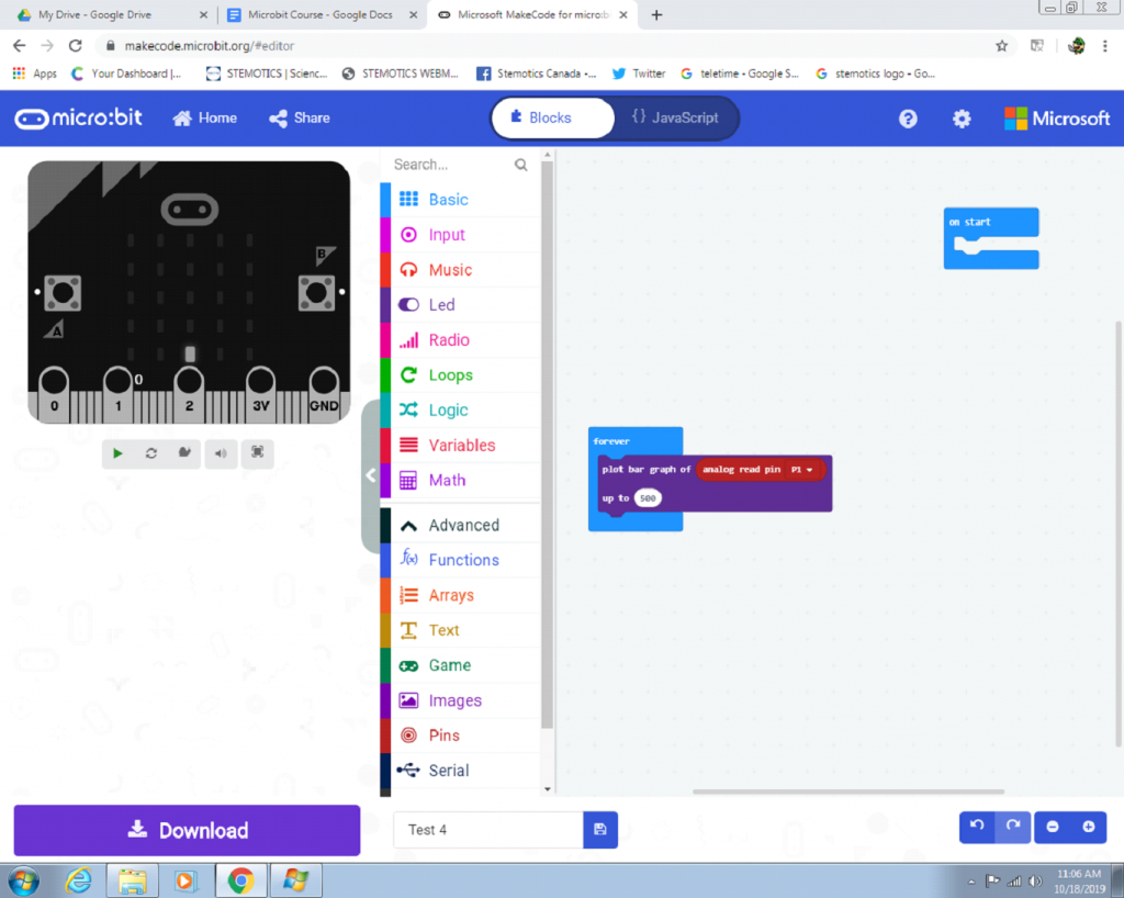
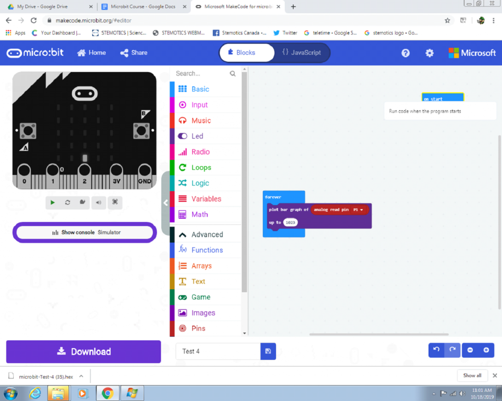
⦁ This is a basic program that uses the Potentiometer to light up the Micro:Bit’s LEDs. You will need a “plot bar graph” block, which can be found in the Led section. Put it into the “forever” loop. Then, take an “analog red pin” block from the Pins section, put it in the top white bubble in the “plot bar graph” block and set the pin to P1. Write the number 1023 in the lower white bubble. Then, run the program and turn the Potentiometer and see what happens.
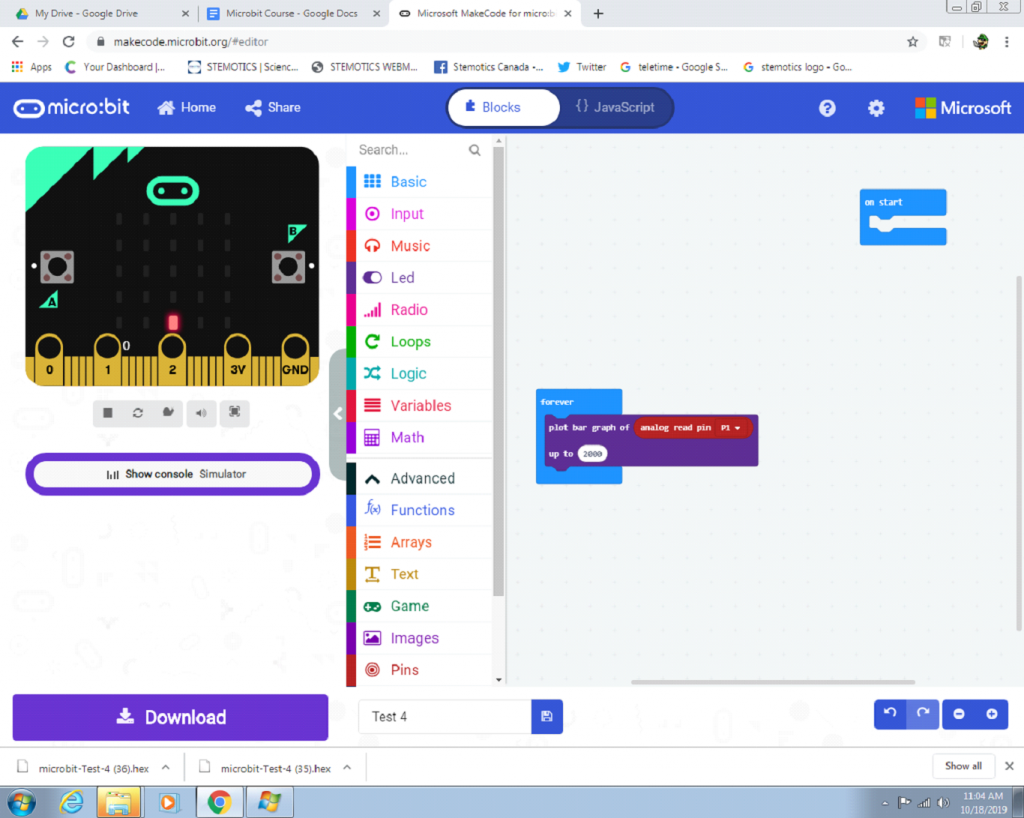
⦁ Try changing the number in the bottom white bubble to a number higher than 1023. When you turn the Potentiometer, less LEDs will light up. Try putting in the number 2000.
⦁ When you change the number to a number lower than 1023, it takes less of turning the Potentiometer to light up all the LEDs. Try putting in the number 500.