Week 2: Hardware
Understanding pin numbering
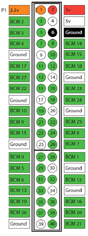
The Raspberry Pi board incorporates a number of General Purpose Input Output (GPIO) header pins, whose behavior can be controlled by Python scripts. On the latest Raspberry Pi boards there are in total 40 header pins, arranged in two rows of 20 on a corner of the board:
Each pin can be referred to numerically. Pin number 1 (“P1”) is at the extreme left on the bottom row in the photo above. This pin provides a 3.3 volt power supply limited to 50mA, and adjacent pin number 2 provides a 5 volt supply. You can work out each pin number from the pin map shown opposite.
There are two numbering options provided on the map, as you can refer to the pin by either by its number on the board (1-40) or you can use the “BCM” name of the connection on the Broadcom system chip to which the pin is physically connected (“BCM 0”-”BCM 27”).
Input and output can be controlled from a Python script for those pins that have BCM names on the pin map. For example, BCM3 (pin number 5) is programmable.
Pin Configuration
Lighting a lamp
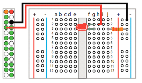
To get started with Raspberry Pi’s GPIO pins you can make a simple circuit to light up a single “lamp” – a Light Emitting Diode (LED). These only allow electricity to pass in one direction so it is important to attach them to the breadboard the right way round. An LED has a long leg and a shorter leg. The long leg goes to the plus side, where the power is coming in.
Directing output
Disconnect the jumper lead power connection from GPIO pin 1, then connect it to pin 7 (BCM4)

Turn on your Raspberry Pi, then begin a new Python script by making attributes and methods available
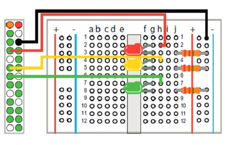
Homework- Adding more lamps
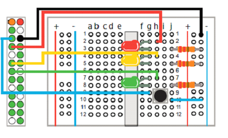
Recognizing input
Turn on your Raspberry Pi then begin a new Python script by making attributes and methods available
⦁ import RPi.GPIO as GPIO
⦁ from time import sleep
⦁ GPIO.setmode( GPIO.BOARD )
⦁ GPIO.setup( 7 , GPIO.OUT )
⦁ GPIO.setup( 5 , GPIO.IN )
i = 1
while i < 4 :
if GPIO.input( 5 ) :
GPIO.output( 7 , False )
else :
GPIO.output( 7 , True ) ;
print( ‘Button Pushed: ’ + str( i ) ) print( ‘\t7 Output True – RED ON’ )
sleep( 1 )
i += 1
⦁ GPIO.cleanup()
⦁
Save the file, then enter this command to run the script with super user privileges and see the LED blink on and off sudo python gpio_input.py