Week 7: Servo Motor
Description:
Use a Raspberry Pi 3 and Python Scripts to control a servo motor. This project uses Python scripts run on a Raspberry Pi microcontroller to send GPIO PWM outputs to a servo motor to set its angle. In the task we’re using them as outputs, to send signals to a servo motor.
Servo Motor
A servo motor is a type of DC motor that, upon receiving a signal of a certain frequency, can rotate itself to any angle from 0-180 degrees. Its 90 degree position is generally referred to as ‘neutral’ position, because it can rotate equally in either direction from that point.
The way a servo motor reads the information it’s being sent is by using an electrical signal called PWM. PWM stands for “Pulse Width Modulation”. That just means sending ON electrical signals for a certain amount of time, followed by an OFF period, repeated hundreds of times a second. The amount of time the signal is on sets the angle the servo motor will rotate to. In most servos, the expected frequency is 50Hz, or 3000 cycles per minute. Servos will set to 0 degrees if given a signal of 0.5 ms, 90 when given 1.5 ms, and 180 when given 2.5ms pulses. This translates to about 2.5-12.5% duty in a 50Hz PWM cycle. If you consider the servo position to range from 0 to 100%, the pulse widths involved range from 0.5ms/20ms (2.5%) and 2.5/20 (12.5%) of the total pulse period
Duty Cycle
When the signal is high, we call this “on time”. To describe the amount of “on time” , we use the concept of duty cycle. Duty cycle is measured in percentage. The percentage duty cycle specifically describes the percentage of time a digital signal is on over an interval or period of time. This period is the inverse of the frequency of the waveform.
If a digital signal spends half of the time on and the other half off, we would say the digital signal has a duty cycle of 50% and resembles an ideal square wave. If the percentage is higher than 50%, the digital signal spends more time in the high state than the low state and vice versa if the duty cycle is less than 50%. Here is a graph that illustrates these three scenarios:
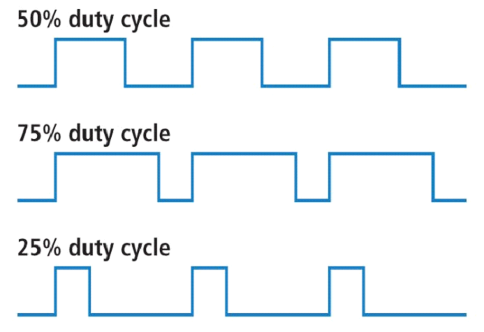
100% duty cycle would be the same as setting the voltage to 5 Volts (high). 0% duty cycle would be the same as grounding the signal.
We’ll be sending PWM signals from one GPIO pin on the RPi, and powering it from the GPIO board, so three wires will run from the servo to the Rpi.
Hardware Required:
Raspberry Pi 3 (RPi)
Jumper Wires, Male to Female (M/F)
Servo Motor
Hardware Setup
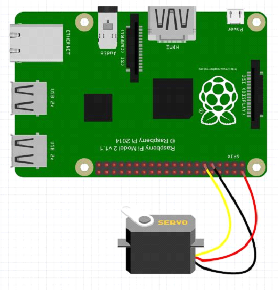
The only thing that you have to do is plug the three wires from the servo into the GPIO board. Refer to the diagram above for the pin numbers.
So, with that out of the way, we are ready to hook up our servo. For our servo, the ground wire is Black, the Red wire is 5 volt, and the white wire is the control line. If you are using a different servo, you will need to read the instructions to see what the color code is for your three wires, but it is likely similar to mine. The sketch below shows how you should hook the servo up. Notice I have the 5V hooked to the Pi physical pin 2, the servo ground hooked to the Pi physical pin 9, and the servo control line hooked to the Pi physical pin 11.
You can also use pulse width modulation to control the angle of a servo motor attached to something mechanical like a robot arm. Servos have a shaft that turns to specific position based on its control line. Our servo motors have a range of about 180 degrees.
Software Setup
First, we need to open a program on the Pi to write our code. We’re going to use IDLE 2, so go to the top left of your desktop, click Menu, click Programming, and click Python 2(IDLE).
The first thing we need to do is import the GPIO module. So, on the first line, type exactly, CaSe sensitive,
import RPi.GPIO as GPIO
this imports the GPIO module
next, we need a command called ‘sleep’, so write
from time import sleep
next we need to name all of the pins, so set the naming mode by writing
GPIO.setmode(GPIO.BOARD)
this sets the names to board mode, which just names the pins according to the numbers in the middle of the diagram above.
Now we need an output to send our PWM signal on, so write
GPIO.setup(11, GPIO.OUT)
Now setup PWM on pin #3 at 50Hz
pwm=GPIO.PWM(11, 50)
Then start it with 0 duty cycle so it doesn’t set any angles on startup
pwm.start(0)
Now, to set the angle of the servo, we need to send a specific signal to it. This can differ from servo to servo, as normally it’s from 2.5-12.5%, and on the ones I’m using it’s 2-12%. Regardless, it will be a 10% window, so to calculate the duty cycle for your desired angle, divide by 18, then add the lowest available value, in this case 2.
So, for 90 degrees, divide by 18, which is 5, then add 2, and you get 7. So on this servo 7% duty is 90 degrees.
As you can see, this math is not very friendly and would be tedious to do every time you wanted to set an angle, so in order to simplify that we’re going to write a function in Python that does the math automatically then sets the angle.
So, first define a function. You can name it whatever you like.
def SetAngle(angle):
duty = angle / 18 + 2
GPIO.output(11, True)
pwm.ChangeDutyCycle(duty)
sleep(1)
GPIO.output(11, False)
pwm.ChangeDutyCycle(0)
Now that probably looks like a lot of confusing code, so let me explain everything I did.
⦁ The first line sets up a function called ‘SetAngle’ that we can call later in the code and give our input as an angle.
⦁ The second line (which needs to be indented inside the function) sets a variable equal to our angle divided by 18 and 2 added like I showed above
⦁ The third line turns on the pin for output
⦁ The fourth line changes the duty cycle to match what we calculated
⦁ The fifth line waits 1 second so the servo has time to make the turn. Depending on the speed of your servo you might need longer, or you might not need this long
⦁ The sixth line turns off the pin
⦁ And the seventh line changes the duty back to 0 so we aren’t continuously sending inputs to the servo
Now in your code you can call the function, by writing
SetAngle(90)
to tell the servo to turn to 90 degrees.
So, in your code, call a few angles, and when we run the code we’ll see how they run on the servo.
At the end of your code, make sure to write
pwm.stop()
GPIO.cleanup()
Final Code:

import RPi.GPIO as GPIO
from time import sleep
GPIO.setmode(GPIO.BOARD)
GPIO.setup(11, GPIO.OUT)
pwm=GPIO.PWM(11, 50)
pwm.start(0)
def SetAngle(angle):
duty = angle / 18 + 2
GPIO.output(11, True)
pwm.ChangeDutyCycle(duty)
sleep(1)
GPIO.output(11, False)
pwm.ChangeDutyCycle(0)
SetAngle(0)
pwm.stop()
GPIO.setwarnings(False);
GPIO.cleanup()