Week 9 – Servo Motor
Arduino
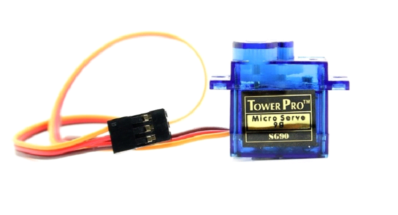
Introduction – Servo Motor
Servo motors are an easy way to add motion to your electronics projects. Originally used in remote-controlled cars and airplanes, they now crop up in all sorts of other applications. They’re useful because you can instruct these small motors how far to turn, and they do it for you.
You ordinary, small DC motor has two hookup wires and simply turns continuously when power is applied. If you want it to spin in the opposite direction, you reverse the power. If you want to know how far it has turned, you’ll need to devise a way to measure that.
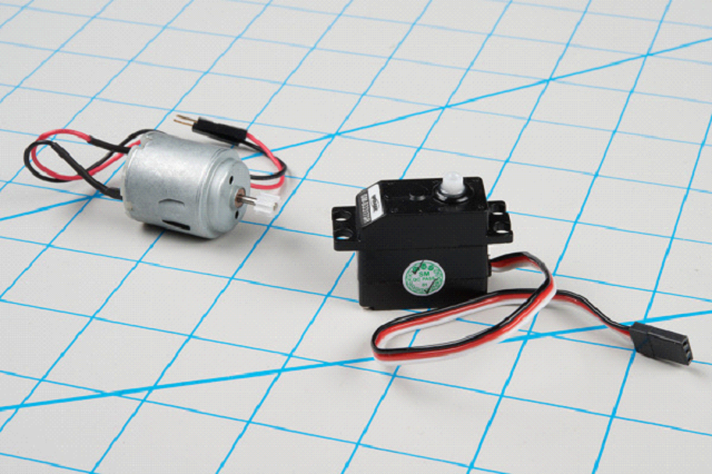
In contrast, you instruct a servomotor where to turn using a command protocol. The servo has three wires – power and ground, plus a third wire, to carry those commands.
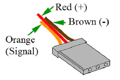
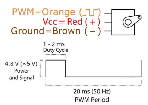
The table below summarizes common color schemes. A useful mnemonic is that the most drab color (black or brown) is usually ground, and red is usually the power supply.
| Pin Number | Signal Name | Color Scheme 1 (Futaba) | Color Scheme 2 (JR) | Color Scheme 3 (Hitec) |
| 1 | Ground | Black | Brown | Black |
| 2 | Power Supply | Red | Red | Red or Brown |
| 3 | Control Signal | White | Orange | Yellow or White |
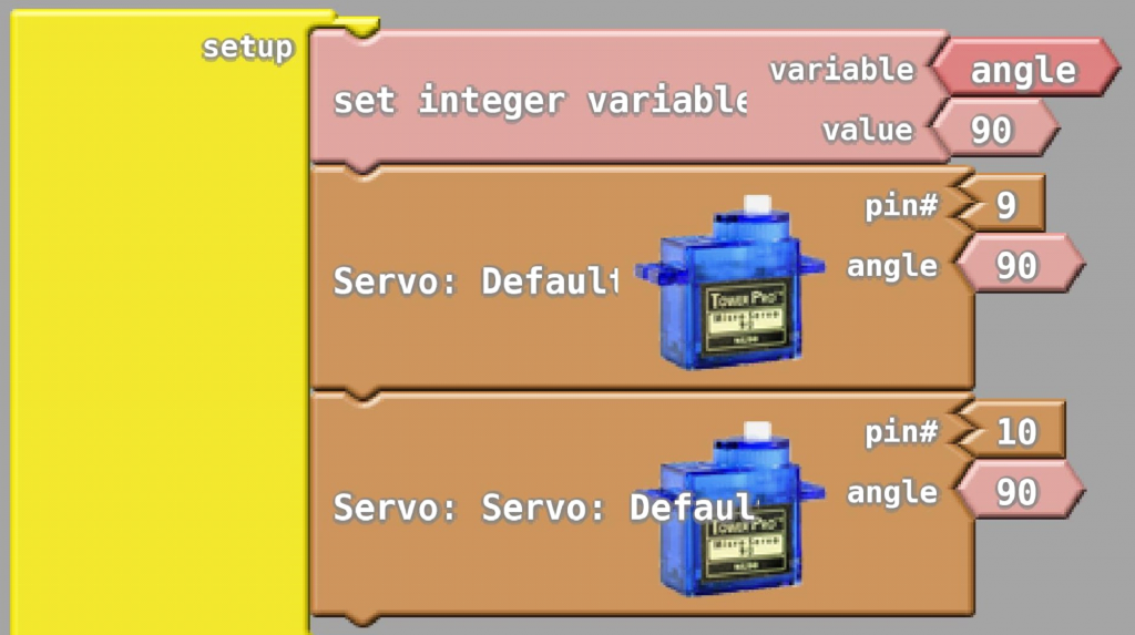
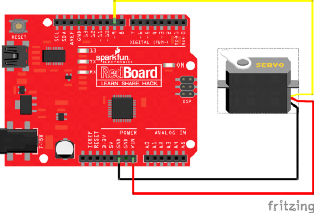
Circuit Diagram:
Practice Exercise:
⦁ Turn 90 Degree
⦁ Turn -90 Degree
⦁ Turn 180 Degree
⦁ Turn -180 Degree
Homework:
Use ultrasonic sensor to sense the distance and move 90 degree when an object closer than 20 cm.
The RED LED should turn ON when the Servo Motor turns 90 degree
The Green LED should turn ON when the Servo Motor comes back to 0 Position.
Example Code